|
|
|
|
|
Pictures of Sample
Implementations |
|
|
|
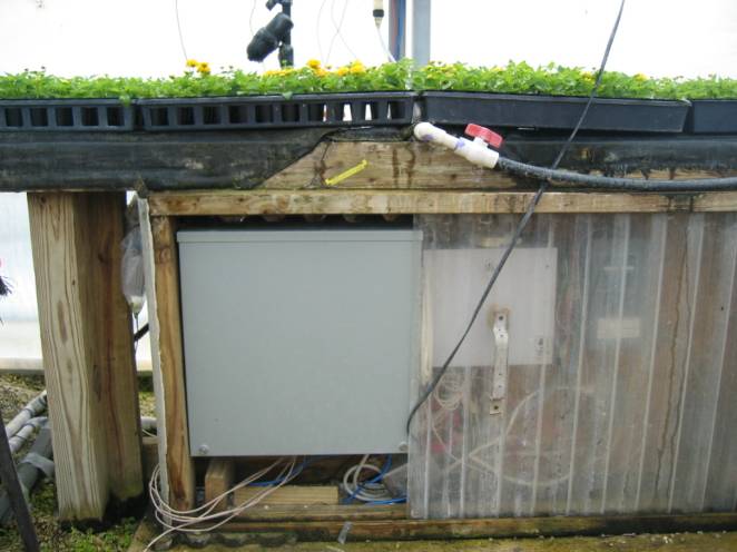
Commercial Greenhouse
Implementation The first two pictures below
show a user-installed iNetGrow system for greenhouse irrigation. The system replaces a timer. Besides time-based irrigation, the
iNetGrow system is programmed to vary the irrigation times according to the
temperature and light level during the summer months. During the winter months, the
relative humidity is also considered in setting the irrigation times. The Apopka controller and the
three smart modules are placed in a metal box under the bench. |
|
|
|
|
|
|
|
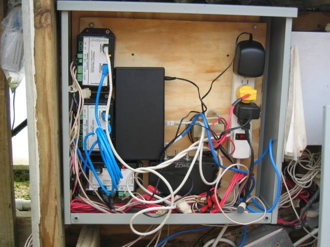
Inside the box, you can see
the controller and the three smart modules daisy-chained to the
controller. The box also houses
the transformers and a homemade switch box. A temperature probe is placed inside the box to monitor
the temperature. The Apopka
controller is connected to the local area network through a wireless
link. Since the metal box would block
the wireless signals, the wireless client is wrapped in plastic and placed
outside the box. In the picture
below, you can see the wireless client immediately to the left of the bench
support leg. |
|
|
|
|
|
|
|
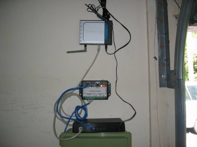
Residential Irrigation System The picture below is taken
from a home-owner implementation of a residential irrigation system. The iNetGrow system allows the user
to monitor his lawn while on vacation through a web page. The script allows both scheduled
irrigations and manual overrides. The system uses the existing
transformer (24VAC). A single
smart module (DO-E) controls four solenoid valves that cover the four
irrigation zones. The Apopka is
connected to the local area network (LAN) through a wireless client, as shown
below. The setup is simply mounted
on the garage wall, since the garage is relatively free from dust and water. |
|
|
|
|
|
|
|
Also see: 1.
What is Agricultural
Control? 4.
Ethernet and Internet
Protocols 5.
Pictures of Sample
Implementations |
|
|

![]()
© Rigel Corporation iNetGrow 2003-2006. All rights reserved.